Torpedo Tubes
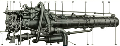
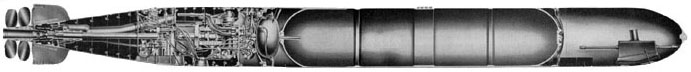
Torpedo tubes on U.S. submarines in World War II were basically large naval guns that used compressed air rather than explosives to eject their projectiles. Most modern submarines use compressed air to force water into the tube, thus ejecting the torpedo with no possibility of air escaping the tube. One marked difference between any torpedo tube and a gun is that the torpedo itself is self-propelling; the tube generally supplies only the initial impetus for the torpedo. Shown above is a view of the outboard side of a tube in a fleet submarine.
World War II era torpedo tubes were complex devices with many interrelated mechanisms and systems:
1. The Barrel, made up of three sections of bronze castings - breech, middle, and muzzle, joined together to form a continuous cylinder. Overall length (not including doors): 252 inches (bow tubes) or 276 inches (stern tubes). Diameter: 21.125 inches.
2. The Breech Door (at inboard or loading end) and the Muzzle Door (at the outboard or ejecting end).
3. Interlocking Mechanisms, which are fitted to submarine tubes to prevent the simultaneous opening of both breech and muzzle doors.
4. The Firing Mechanism, which releases compressed air into the tube to launch the torpedo.
5. The Poppet Valve System, which removes the air used to fire the torpedo from the tube, and vents it back into the boat, thus preventing its escape through the muzzle door and out into the water.
6. The Torpedo Setting Mechanisms, consisting of the Depth Setting, Gyro Setting, and Speed Setting (Mark 14 torpedoes only) Mechanisms.
7. The Tripping Latch, which, when the torpedo starts out of the tube, engages and trips the starting lever (a trigger-like projection from the torpedo) to start the torpedo's engine; and the Torpedo Stop Bolt, which fixes the torpedo in the tube so the depth, gyro, and speed setting sockets in the torpedo will line up with their respective spindles on the tube.
8. The Tube Flood and Drain System, which provides the means of flooding, venting, and draining of the tube, before and after firing a torpedo.
9. The Electric Firing and Indicating System, which consists of the Torpedo Control Circuit, the Torpedo Firing Circuit, and the Torpedo Battle Order and Ready Light Circuit.
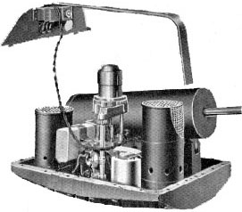
 The
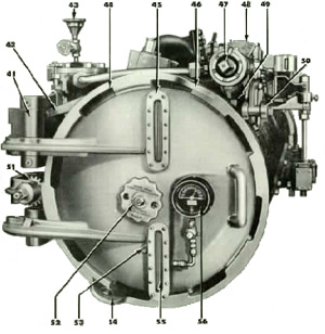
breech door is the loading end of the torpedo tube. Here it is shown with its
related mechanisms, and the other operating mechanisms surrounding it.
The
breech door is the loading end of the torpedo tube. Here it is shown with its
related mechanisms, and the other operating mechanisms surrounding it.
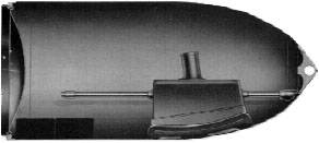
At the other end of the tube is the muzzle door, which opens out into the water. The muzzle doors of bow tubes are equipped with shutters that open and close with the muzzle doors. The shutters help to streamline the bow, so that the speed of the submarine is not affected while bow tubes are not in use.
Both breech and muzzle doors are operated by mechanisms located at the breech end of the tube inside the submarine. Interlocking devices are fitted to submarine tubes to prevent the simultaneous opening of both breech and muzzle doors, thus preventing catastrophic flooding through the 21-inch barrel.
 Settings
for depth, gyro angle, and speed are made by spindles that penetrate the tube
and engage their respective spindles in the torpedo.
Settings
for depth, gyro angle, and speed are made by spindles that penetrate the tube
and engage their respective spindles in the torpedo.
The depth setting index dial is graduated in feet from 0 to 50, and its setting shaft is operated by a hand crank.
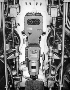
The gyro setting mechanism inputs the angle of travel the torpedo takes after leaving the tube, allowing the Commanding Officer to attack without having to aim his submarine directly at the target. The gyro angles in all torpedoes in one nest of torpedo tubes are set by the gyro setting indicator-regulator, shown at left.
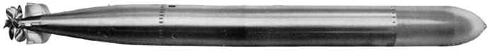
The most commonly used torpedo by the U.S. during World War II was the Mark 14 steam driven torpedo. In it was a mechanism for setting the speed on either low or high. A Mark 14 set on low speed would travel at about 32 knots with a range of approximately 9,000 yards, and on the high speed setting at about 47 knots with a range of 4,500 yards. Since experience showed that the effective range of the weapon was far short of its maximum range, the low speed setting was rarely (though not never) used. The speed setting spindle on the tube is operated by a hand crank.
Before firing a torpedo, the tube must be flooded from tanks located within the submarine. This is done in order to equalize the pressure inside the tube with the pressure from outside, so the muzzle door may be opened against the resistance of the sea. Also, using water from tanks within the vessel avoids disturbing the trim of the boat. Similarly, water that enters the tube after the firing of a torpedo is drained into a tank, helping to compensate for the loss of the 3,000+ pound torpedo.
Most U.S. fleet submarines like Bowfin had six bow tubes (two vertical rows of three each) and four stern tubes (two vertical rows of two each). The tubes were normally carried loaded, with ten reloads on racks forward, and four reloads aft, for a total of 24 torpedoes
exploder
warhead
front torpedotubes 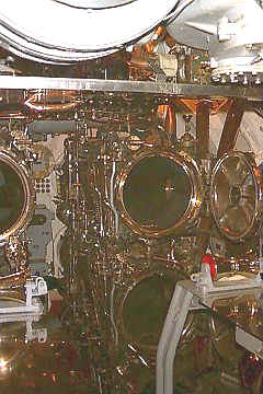
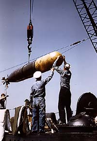 loading torpedoes to an u.s. submarine
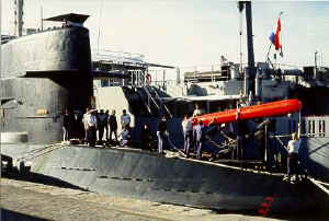
new torpedoworkschip Hr.Ms Mercuur 4
reloading HrMs Zwaardvis
with an red/orange exercisetorpedo mark 48
"hey mates"
Most information on this page is taken from 21-Inch Submerged Torpedo Tubes, Marks 32 to 39 and Modifications as in SS198 and up, Bureau of Ordnance Publication - Ordnance Pamphlet 1085, June 1944.
[Torpedoes] [Torpedo Tubes] [Sonar] [Engines] [Periscopes] [TBT] [Deck Armament]
